Series Roadmap
| # | Topic | Status |
|---|---|---|
| 1 | What is RISC-V? | ✅ |
| 2 | What is an instruction: encoding and formats | ✅ |
| 3 | The macro pipeline and each unit’s hardware structure | 🔲 |
| 4 | Pipeline in depth: hazard handling and branch prediction | 🔲 |
| 5 | Summary, advanced microarchitecture, other CPU architectures | 🔲 |
An Instruction Is, in the End, a 32-bit Number
In part 1, the ISA was the contract between hardware and software. The smallest unit of that contract is the instruction.
Assembly notation like add x5, x6, x7 is for humans to read. What the CPU actually receives is 32 zeros and ones.
What a human writes:   add x5, x6, x7
What the CPU receives:  0000000 00111 00110 000 00101 0110011
                        (a single 32-bit number)
The CPU’s first step in executing an instruction is interpreting these 32 bits — which operation, which registers, whether there is a constant — read off from bit positions. This interpretation is called decoding.
The rules for which bits hold what are the instruction format.
Why a Small Set of Fixed Formats
CISC has variable instruction lengths, and field positions differ per instruction. A decoder must first find the instruction’s boundary and type before it can read the next field.
RISC-V is the opposite. Base instructions are all 32 bits fixed length, with field positions standardized into a small set of formats.
The benefit of this regularity is decoding speed. With fixed field positions, the decoder can extract the bits it needs in parallel, even before fully identifying the instruction type. In particular, it can read register numbers immediately and start accessing the register file early. This simplicity is the foundation for the pipelined execution covered in part 3.
RISC-V’s base integer instructions have six formats.
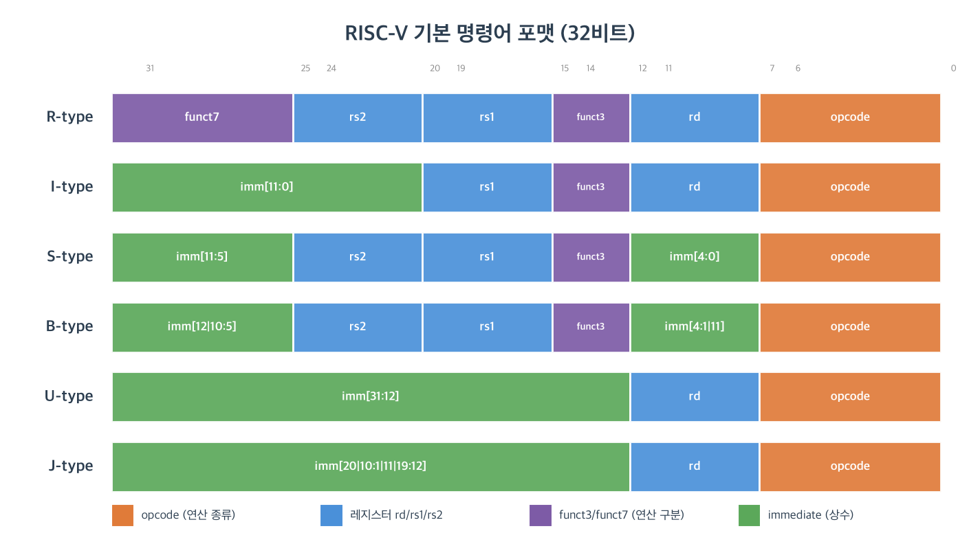
| Format | Purpose | Representative instructions |
|---|---|---|
R |
Register-register operations | add, sub, and, sll |
I |
Immediate operations, loads, jalr | addi, lw, jalr |
S |
Stores | sw, sb |
B |
Conditional branches | beq, bne, blt |
U |
Upper 20-bit immediate | lui, auipc |
J |
Unconditional jumps | jal |
Common Fields: Why Registers Are Always in the Same Place
Look at the blue (register) fields in the figure above: their positions stay nearly fixed even as the format changes.
opcode(bits 6:0): same place in every format. Sets the operation’s major class.rd(bits 11:7): destination register. Same place in R/I/U/J.rs1(bits 19:15): first source register. Same place in R/I/S/B.rs2(bits 24:20): second source register. Same place in R/S/B.funct3(bits 14:12),funct7(bits 31:25): distinguish sub-operations within one opcode.
This is deliberate. Because rs1 and rs2 are always at bits 19:15 and 24:20, the decoder sends those bits straight to the register file as addresses before determining the instruction type. Register reads proceed overlapped with decoding. Had register positions differed per format, registers could only be read after the type was determined — a delay.
funct3 and funct7 supplement the opcode. For example, add and sub share opcode and funct3, differing only in funct7 (0000000 vs 0100000) — a hierarchy dividing sub-operations within one major class.
The Formats in Detail
R-type: Register-Register Operations
Computes from two source registers into a destination register. No immediate.
add x5, x6, x7   →  x5 = x6 + x7   (funct7 0000000, funct3 000)
sub x5, x6, x7   →  x5 = x6 - x7   (funct7 0100000, funct3 000)
and x5, x6, x7   →  x5 = x6 & x7   (funct7 0000000, funct3 111)

Bit example (add):
funct7   rs2   rs1   funct3   rd    opcode
0000000  00111 00110 000      00101 0110011
   |      x7    x6    ADD      x5    OP
add and sub differ by funct7; add and and differ by funct3. All three share the opcode.
I-type: Immediate Operations and Loads
Computes from one source register and a 12-bit immediate. Loads are also I-format (address = base register + offset).
addi x5, x6, 10   →  x5 = x6 + 10            (immediate op)
lw   x5, 8(x6)    →  x5 = memory[x6 + 8]      (load)
jalr x1, x6, 0    →  x1 = PC+4, PC = x6 + 0   (jump via register)

Bit example (addi):
imm[11:0]     rs1   funct3   rd    opcode
000000001010  00110 000      00101 0010011
The three do different things — immediate arithmetic, a memory load, a register jump — yet all are I-format, because they share the same structure of one source register and a 12-bit immediate. The 12-bit immediate is signed, ranging -2048 ~ +2047.
S-type: Stores
Writes a register value to memory. Since the destination is a memory address, not a register, there is no rd. Instead the immediate (offset) is split into two pieces.
sw x7, 8(x6)   →  memory[x6 + 8] = all 4 bytes of x7   (funct3 010)
sh x7, 8(x6)   →  memory[x6 + 8] = low 2 bytes of x7   (funct3 001)
sb x7, 8(x6)   →  memory[x6 + 8] = low 1 byte of x7    (funct3 000)

Bit example (sw):
imm[11:5]  rs2   rs1   funct3   imm[4:0]  opcode
0000000    00111 00110 010      01000     0100011
The three distinguish the store width via funct3 (word/halfword/byte). The lower 5 bits of the immediate go into the rd slot (bits 11:7). Even split this way, rs1 and rs2 keep their positions.
B-type: Conditional Branches
Compares two registers and, if the condition holds, moves the PC relatively. Similar to S, but the immediate encodes a branch offset.
beq x6, x7, LABEL   →  branch if x6 == x7   (funct3 000)
bne x6, x7, LABEL   →  branch if x6 != x7   (funct3 001)
blt x6, x7, LABEL   →  branch if x6 <  x7   (funct3 100, signed compare)

Bit fields:
imm[12|10:5]  rs2   rs1   funct3   imm[4:1|11]  opcode
The three distinguish the compare condition via funct3 (equal/not-equal/less-than). Branch offsets are in 2-byte units (the lowest bit is always 0), so 12 bits express a ±4KB range. The reason the bit order is scrambled is explained below.
U-type: Upper 20-bit Immediate
Places a 20-bit immediate in the upper 20 bits of the result. Used for large constants or addresses.
lui   x5, 0x12345   →  x5 = 0x12345000            (constant in upper bits)
auipc x5, 0x12345   →  x5 = PC + (0x12345 << 12)   (PC-relative address)
The base integer ISA’s U-type instructions are exactly these two, lui and auipc. Unlike other types, there are only two examples because the U-format exists solely for these two uses (absolute upper-bit constant, PC-relative upper-bit address). Combining lui and addi builds an arbitrary 32-bit constant in two instructions.
J-type: Unconditional Jumps
jal (jump and link) moves the PC relatively while saving the return address in rd. Used for function calls.
jal x1, FUNC → x1 = PC + 4 (return address), PC += offset
The base integer ISA’s only J-type instruction is jal. The jalr used to return from a function specifies its destination via a register (register + fixed offset), so it is I-type, not J. In other words, a jump splits by how the target is given: as an immediate it is J (jal), via a register it is I (jalr). Jump offsets, like branches, are in 2-byte units (the lowest bit is always 0), so jal’s 20-bit immediate jumps a ±1MB range.
The Puzzle of Immediate Encoding
Look at the S, B, and J formats and the immediate bits are scattered oddly. Notations like imm[12|10:5] and imm[4:1|11] mean the immediate’s bits are not contiguous within the instruction but placed out of order. Why make this so complicated?
The reason is to preserve two invariants.
1. Fixed register field positions
As seen above, rs1, rs2, and rd must sit at the same bits in every format. Since the immediate cannot intrude on those slots, it is fragmented into the remaining bits. This is the price of preserving the benefit of reading registers first.
2. Fixed sign-bit position
Every immediate’s most significant sign bit is placed so that it always lands at bit 31 of the instruction.
Sign-extension hardware:
  Whatever the immediate width, the sign bit is always instruction[31]
  → the sign-extension circuit only needs to look at instruction[31] (simple, fast)
With a fixed sign-bit position, the sign-extension circuit is simple. Whether 12 or 20 bits, it takes instruction bit 31 as the sign and fills the upper bits. Had the sign-bit position differed per format, sign extension would have to wait for format determination — a slowdown.
The cost of reassembling the immediate bits is only wiring (a multiplexer). This rearrangement happens in parallel and is not on the critical path. Complex for a human to read, but a favorable trade for hardware — a signature example of RISC-V’s pragmatism.
Decoding: Splitting 32 Bits into Fields
To summarize, the CPU’s decoder takes a 32-bit instruction and performs the following in parallel.
32-bit instruction
      │
      ├─ opcode[6:0]      → determine operation major class
      ├─ rs1[19:15]       → start register-file read (immediately)
      ├─ rs2[24:20]       → start register-file read (immediately)
      ├─ rd[11:7]         → hold destination register number
      ├─ funct3, funct7   → finalize sub-operation
      └─ immediate        → reassemble + sign-extend
All of these extractions happen simultaneously thanks to fixed bit positions. The regularity of instruction formats is decoding speed itself — the reason the pipeline in the next part can stream one instruction through every clock.
References
The full instruction list and exact encoding of the base integer ISA (RV32I) can be found here.
- Official specification: The RISC-V Instruction Set Manual, Volume I: Unprivileged ISA — the RV32I base integer chapter defines the bit encoding of every instruction.
- ISA reference card (one page): jameslzhu/riscv-card — a one-page card summarizing the six formats and base instructions. The format figure in this post follows the same structure.
The RV32I base set comprises about 40 instructions. The examples in this post are just the representatives of each format.
Summary
| Item | Detail |
|---|---|
| Instruction | 32-bit fixed-length number |
| Formats | R / I / S / B / U / J — six of them |
| Common fields | opcode, rd, rs1, rs2, funct3/7 at fixed positions |
| Fixed registers | register reads can start before decoding completes |
| Scattered immediate | to fix register positions + the sign bit (always [31]) |
| Decoding | field extraction in parallel thanks to fixed positions |
RISC-V instructions are 32-bit fixed length, with field positions standardized into six formats. Fragmenting the immediate to keep registers and the sign bit at fixed positions is a decision that sacrifices human readability to gain hardware decoding speed. Having seen what an instruction is and how it is encoded, the next part enters the structure by which the CPU actually executes these instructions — a macro view of the five stages one instruction passes through, and the hardware units responsible for each.
Next: RISC-V CPU #3 — the macro pipeline and each unit’s hardware structure (upcoming)